
Start With the Marine Operating Environment, Not the Thread Size
Selecting marine hydraulic fittings involves far more than matching a hose bore to a familiar thread. A fitting that performs reliably inside a protected machinery space may deteriorate quickly on an exposed deck, near a splash zone, or in equipment repeatedly washed down with salt water. Before comparing catalogs, define each assembly’s external exposure, hydraulic fluid, working pressure, temperature range, vibration, movement, and maintenance access. These conditions—not the thread designation—determine which material, sealing method, geometry, and hose construction you should consider.
Marine systems impose several simultaneous risks. Salt deposits retain moisture and accelerate corrosion, while vibration and pressure pulsation can loosen poorly supported connections or fatigue the hose near its ferrule. Tight routing places side loads on angled fittings, and incompatible metals create galvanic corrosion once they are electrically connected in the presence of seawater. Reliable marine hydraulic fittings must therefore be chosen as part of a complete, validated hose assembly rather than as isolated hardware pulled from a bin.
Classify every installation by severity. A sheltered power-unit connection faces very different conditions from a steering line, deck crane, winch, hatch actuator, or exposed loading arm. Record whether the fitting will see direct seawater contact, condensation, chemical washdown, submersion, abrasive contamination, or frequent disconnection. Identify project specifications, vessel requirements, and applicable classification-society rules early, because they may restrict materials, assembly methods, inspection intervals, or traceability documentation before you ever place an order.
Which Fitting Materials Survive Salt Water and Which Fail?
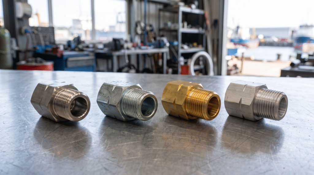
Stainless steel is the default choice for exposed marine service because it pairs mechanical strength with genuine corrosion resistance. Grade 316 or 316L generally outperforms 304 in chloride environments thanks to its molybdenum content, but it is not immune to pitting or crevice corrosion. Stagnant salt deposits, scratched surfaces, oxygen-starved crevices under clamps, and improper cleaning can all trigger localized attack. The comparison in this 304 vs 316 stainless steel fittings selection guide helps procurement teams weigh the two grades against a specific exposure profile instead of defaulting to the cheaper option.
Carbon steel offers high strength and broad availability for hydraulic service. With an appropriate plated or coated finish it can be practical in enclosed, dry, or otherwise controlled spaces. However, coating damage during crimping, tool contact, or operation exposes the bare substrate, and rust then spreads from that point. Carbon steel used anywhere near salt water demands a defined inspection and replacement plan. Confirm coating compatibility, corrosion performance, and any end-user restrictions rather than assuming durability from a clean appearance out of the box.
Brass gives useful machinability and acceptable corrosion behavior in selected low- and moderate-pressure applications, but alloy composition matters because some brasses suffer dezincification in seawater. Aluminum is lightweight, yet its pressure capability, wear resistance, and galvanic relationship with surrounding metals all require careful review. Never mix materials solely for availability. If dissimilar metals are unavoidable, assess their galvanic potential, limit electrolyte contact where practical, and follow approved isolation and bonding practices. Material choice must also account for hydraulic-fluid compatibility, seal compounds, temperature, and the mechanical rating of the finished connection.
Permanent, One-Piece, and Reusable Fitting Designs Compared
Permanent swaged or crimped fittings dominate applications that need a controlled, production-quality hose assembly. A stem is inserted into the hose and a ferrule is compressed to a specified diameter, producing the required retention and sealing geometry. Performance depends on the exact hose, fitting, ferrule, crimp diameter, tooling, and procedure being validated together as a system. A ferrule that merely looks dimensionally similar is not automatically interchangeable. Thermoplastic hose, for example, may require a dedicated component such as a ferrule for SAE 100R7 hose matched to that specific reinforcement.
One-piece fittings integrate the stem and ferrule into a single unit. They simplify inventory, reduce component-selection errors, and support fast repetitive production when paired with approved hoses and crimp data. Two-piece fittings use separate stems and ferrules, offering flexibility across hose constructions but demanding disciplined component control so mismatched parts never reach the crimper. Neither format is universally superior; the correct choice depends on the hose family, pressure cycle, available tooling, production volume, routing constraints, and qualification requirements for the vessel.
Reusable or field-attachable fittings earn their place where crimping equipment is unavailable or an approved field-repair strategy requires them. They should not be treated as universal emergency substitutes. Assembly technique, hose compatibility, pressure rating, and inspection criteria remain critical to a safe result. For machinery where leakage could affect steering, lifting, personnel safety, or environmental protection, repairs must follow the equipment manufacturer’s procedure and applicable vessel rules. A temporary connection should never be quietly promoted to permanent service without engineering review and a documented pressure test.
Thread and Seal Identification Prevents Expensive Mismatches
Thread diameter alone never identifies a hydraulic connection. Marine and internationally sourced equipment may use BSPP, BSPT, JIC, SAE, ORFS, NPT, metric DIN, or JIS interfaces. Several share similar diameters and pitches yet rely on different seat angles or sealing mechanisms. A BSPP connection, for instance, may seal through a bonded washer, an O-ring, or a defined cone seat depending on its design. A BSPP male 60-degree cone seat swaged fitting must be matched to the corresponding female cone seat, not merely to any port that happens to accept the thread.
JIC fittings typically seal on a 37-degree flare, while many JIS and BSP-related connections use a 60-degree cone. ORFS connections seal through an O-ring compressed against a flat face and are often specified where vibration control and leak resistance are priorities. NPT connections use tapered threads and normally require a compatible thread sealant applied per procedure. Flare and cone connections seal at their metal seating surfaces; wrapping PTFE tape onto those threads will not correct a damaged or mismatched seat and only introduces contamination into the system.
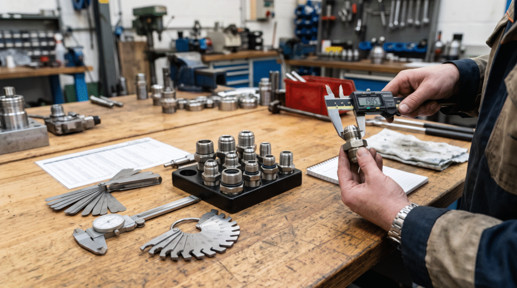
Identify an unknown fitting methodically: measure the male outside diameter or female inside diameter, check pitch with a thread gauge, determine whether the thread is parallel or tapered, and inspect the sealing surface. Use a recognized identification chart rather than visual judgment, and confirm the seat angle with the proper gauge whenever two similar standards are possible. A 90-degree JIS gas female 60-degree cone fitting shows why the thread standard, seat form, orientation, and hose end must all appear on the specification, not just a nominal size.
Pressure Ratings Are Only One Part of Hose Compatibility
The working pressure of an assembly is capped by its lowest-rated element—hose, fitting, adapter, seal, or port. Selection should account for maximum continuous pressure, transient spikes, impulse frequency, temperature, and any vacuum condition on suction lines. Do not size from nominal system pressure alone. Deck machinery, steering systems, and lifting equipment generate dynamic loads that are invisible on a static gauge. Where the data are uncertain, obtain the equipment duty cycle and pressure history before you finalize the assembly and its safety margin.
Hose construction must match the fitting and ferrule as a set. Wire-braid, multi-spiral, textile-reinforced, and thermoplastic hoses differ in cover thickness, reinforcement behavior, and crimp requirements. High-pressure spiral hoses often demand dedicated ferrules, skiving instructions, and fitting stems; a component such as a ferrule for R12, R20, or R24 hose should be used only within a confirmed hose-and-fitting combination and never carried across to a hose it was not tested with.
Temperature acts on the tube, cover, reinforcement, seals, and fluid at once. Elevated fluid temperatures shorten hose life, while cold conditions reduce flexibility and raise stress during movement. Verify chemical compatibility with mineral oil, water-glycol fluids, biodegradable hydraulic fluids, fuel, cleaning agents, and any other media present on the vessel. Fire resistance, electrical conductivity, permeation, and low-temperature behavior may each become relevant depending on the fitting’s location and the outcome of the risk assessment.
How Routing and Geometry Influence Fitting Service Life
Straight, 45-degree, and 90-degree fittings are not interchangeable routing conveniences. The chosen geometry should let the hose approach its connection without twisting, side loading, or bending inside the minimum bend radius. A hose bent immediately behind the ferrule concentrates stress exactly where the assembly is least able to flex, and that spot becomes the first failure point. When movement is expected, provide enough length for a broad, controlled bend while keeping the hose clear of structure, sharp edges, hot surfaces, and neighboring lines.
Use angled fittings or adapters to improve routing when they genuinely reduce hose strain, but resist adding unnecessary connections. Every extra interface is another potential leak point, pressure restriction, and inspection location. Elbows should be clocked to their design orientation before final tightening or crimping, not twisted into place afterward. Where a hose moves under pressure, clamps and guards must control that motion without crushing the cover or preventing the required articulation of the line.
Flow requirements also drive fitting size and geometry. An undersized bore or an abrupt change in direction raises velocity, pressure drop, turbulence, and heat. This matters most on return and suction lines, where restrictions contribute to sluggish performance or pump-inlet cavitation. Review both the nominal connection size and the fitting’s internal passage, because a larger thread designation does not guarantee an unrestricted flow path through the complete assembly. Inspect the actual bore of angled fittings, which often narrows at the bend.
A Step-by-Step Specification Checklist for Buyers and Engineers
Begin the purchasing specification with the hose standard, size, pressure class, reinforcement type, and compatible fitting series. Then define each end connection by standard, thread size and pitch, gender, seat or seal type, and orientation. For angled ends, state the required clocking relationship between the two ends. Add material grade, surface finish where relevant, seal compound, overall assembly length, protective sleeve requirements, cleanliness expectations, and any project-specific testing or documentation the vessel demands.
Next, describe the operating context in the same document: hydraulic medium, continuous and peak pressure, fluid and ambient temperature, impulse duty, external seawater exposure, movement, bend constraints, and fire or abrasion hazards. Keep wetted-fluid compatibility separate from external corrosion resistance—these are distinct selection questions with different answers. If you are reproducing an existing sample, supply calibrated measurements and clear photographs, but do not rely on a sample alone when the original thread, material, or pressure rating is unknown.
For production orders, request clear part identification and lot traceability appropriate to the application. Confirm that the manufacturer can control machining, material verification, crimp parameters, dimensional inspection, pressure or leakage testing, and change management. Custom hydraulic configurations should be reviewed as engineered assemblies, especially when you are replacing obsolete parts or joining equipment built to different regional standards. Early technical clarification almost always costs less than correcting incompatible fittings discovered after installation and sea trials.
Installation, Inspection, and Replacement Decisions at Sea
Before assembly, inspect threads, cones, flare faces, O-ring grooves, and hose ends for damage or contamination. Keep clean caps fitted until installation, use only the specified seals, and lubricate them only when the approved procedure allows it. Tighten every connection by the fitting or equipment manufacturer’s method rather than by applying maximum available force. Under-tightening leaks; over-tightening cracks seats, distorts sealing faces, extrudes O-rings, and damages ports. Prevent hose twist by using a proper backup wrench and watching the printed lay line on the hose throughout tightening.
After installation, verify routing, bend radius, clamp position, clearance, and fitting orientation before you pressurize anything. Run the initial pressure test under a controlled procedure that keeps personnel away from potential leak paths. Never search for a high-pressure pinhole leak with a bare hand—injected hydraulic fluid causes severe injury that may not look serious at first. Use an appropriate detection method, and always depressurize the system before adjusting a connection. Repeated tightening is not a remedy for incompatible threads or a damaged sealing surface.
Routine inspections should hunt for red rust, pitting, crevice attack, coating loss, salt accumulation, wetness around seals, cover cracking, abrasion, exposed reinforcement, blistering, fitting movement, and deformation near the ferrule. Replace an assembly when damage exceeds the approved acceptance criteria or when service history is uncertain in a critical line. Recording installation dates, operating locations, failure modes, and inspection findings supports lifecycle tracking and helps engineering teams refine future material and routing decisions across the fleet.
FAQ
Is 316 stainless steel always required for marine hydraulic fittings?
No. It is often preferred for exposed chloride environments, but suitability depends on pressure, location, crevice conditions, fluid compatibility, maintenance access, and project requirements. Protected installations may permit other materials with suitable corrosion protection and a defined inspection plan.
Can BSPP and JIS 60-degree fittings be connected if the threads fit?
Not safely on thread fit alone. Similar-looking connections may differ in thread dimensions, seat geometry, or sealing method. Identify both standards, confirm the seat angle with a gauge, and verify the mating seat before assembly.
Should PTFE tape be applied to every hydraulic fitting thread?
No. Flare, cone, and O-ring fittings seal at dedicated surfaces rather than at the threads, so tape only risks contamination there. Tapered pipe threads such as NPT may require an approved compatible sealant, applied without letting debris enter the hydraulic system.
What causes a hose to fail close to the ferrule?
Common causes include an incorrect hose-and-fitting combination, wrong crimp diameter, excessive bending immediately behind the fitting, hose twist, side loading, abrasion, pressure spikes, and sustained temperature exposure that ages the cover and tube.
Can a corroded marine fitting be cleaned and returned to service?
Light surface deposits may be removable under an approved maintenance procedure, but pitting, coating failure, damaged threads, or attack near sealing and load-bearing areas requires engineering assessment and usually replacement rather than reuse.
What information is needed to order a custom marine hydraulic hose assembly?
Provide the hose type and size, working and peak pressure, temperature, fluid, end standards, thread sizes and pitch, seat types, materials, fitting angles and orientation, assembly length, environmental exposure, and any applicable testing or documentation requirements.